Entries categorized as ‘Matthew Lutz’
final rendering…
December 10, 2008 · Leave a Comment
Categories: Matthew Lutz
Tagged: aggregation, glass, spicules
new crane trajectory
December 2, 2008 · Leave a Comment
Categories: Matthew Lutz
Tagged: rotation, trajectory
new spicule geometry
November 23, 2008 · Leave a Comment
Categories: Matthew Lutz
Tagged: aggregation, glass
more sizes, more directions…
October 22, 2008 · Leave a Comment
Categories: Matthew Lutz
Tagged: aggregation, density, glass, growth, porosity
ML_Possible Trajectories
October 10, 2008 · Leave a Comment
Categories: Matthew Lutz
Tagged: trajectories
ML_Spicule Growth
October 10, 2008 · Leave a Comment
Categories: Matthew Lutz
Tagged: aggregation, growth, rhinoscript
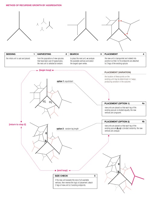
Method of Recursive Growth by Aggregation
October 3, 2008 · Leave a Comment
1. SEEDING:
The first spicule unit is cast and set into place.
// {begin loop} //
2. HARVESTING:
New spicules are continually being cast in 4 unit sizes. From this population of varying sizes, the next unit to be placed is chosen at random.
3. SEARCH:
To find a location for the new piece, the spicules which have already been placed are measured for the largest available open vertex. If no open vertex is large enough to accommodate the new unit, then proceed to step 5.
4. PLACEMENT:
The unit is transported and rotated into position so that 2 of its endpoints are in contact with 2 legs of an existing spicule. Due to the unequal angles of the unit (90/135/135), there are 2 possible rotational placements within any given vertex.
In addition, there are 2 possible methods for determining the location of the new endpoints along the existing legs. With Option 1 (4a) both endpoints of the new unit are placed at an equal distance from the vertex. In Option 2 (4b) one endpoint is placed at a random distance (B) from the vertex, and the other falls where it may (C) along the opposite leg.
5. SIZE CHECK:
If it is determined that the new unit exceeds the size of all available vertices, then the logic of placement is reversed. First, all endpoints are analyzed to find the furthest pair that will fit within the vertex of the new unit. These 2 points will necessarily be from 2 different spicules, which breaks the logic of subdividing and allows the system to grow in a new direction. The new spicule is placed so that these two endpoints are now inside of one of its angles, in contact with 2 of its legs.
// {end loop} //
// {return to step 2} //
Categories: Matthew Lutz


