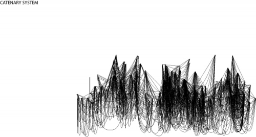
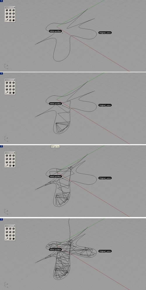
This is the original v.0.1 script. It will eventually crash if the original curve is very intricate (the curves created by the script will become shorter than the tolerance returning a “string required” error…
Anyway, here is the code:
Option Explicit
‘Script written by Ado
Call Main()
Sub Main()
Dim arrStartPt()
ReDim Preserve arrStartPt(0)
arrStartPt(0) = Rhino.GetPoint (“select start point”)
Dim strCrv : strCrv = Rhino.GetObject (“select boundary curve”, 4)
Dim i, j, l, arrNewPt, strTempLn, arrCCX, arrNewTempPt, strNewLine, dblCrvLength
Dim dblAngle : dblAngle = 10
Dim k : k = 10
For j = 1 To 100
ReDim Preserve arrStartPt(j)
arrNewPt = Rhino.Polar (arrStartPt(j-1), k, 10000)
strTempLn = Rhino.addLine (arrStartPt(j-1),arrNewPt)
arrCCX = Rhino.CurveCurveIntersection (strTempLn, strCrv)
If arrCCX(i,0) = 1 Then
arrNewTempPt = arrCCX(0,1)
End If
Call Rhino.DeleteObject (strTempLn)
strNewLine = Rhino.AddLine (arrStartPt(j-1),arrNewTempPt)
dblCrvLength = Rhino.CurveLength (strNewLine)
k = k + (134 – dblCrvLength)
strNewLine = Rhino.ScaleObject (strNewLine,arrStartPt(j-1),array(0.9,0.9,0.9))
arrStartPt(j) = rhino.CurveEndPoint (strNewLine)
Next
Dim arrNewStartPt()
For l = 0 To UBound(arrStartPt)
ReDim Preserve arrNewStartPt(l)
arrNewStartPt(l) = array(arrStartPt(l)(0),arrStartPt(l)(1),arrStartPt(l)(2)+(l*10))
Next
Call Rhino.AddCurve (arrNewStartPt)
End Sub
Categories: Adolfo Nadal
DRIPPING CIRCLES
This early attempt tries to simulate dripping material from overhead. The drip point moves along a path–here a simple sine curve path. Layers are added on top of each drip point with circles of random radii to simulate different amounts of material.

Dripping Circles (Plan)Dripping Circles (Perspective View)
Categories: Joe McGrath
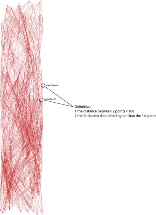
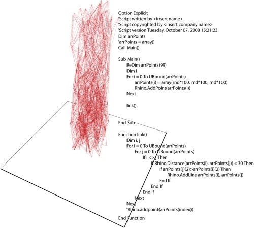
In this process, at first a chunk of randomized points cloud was established.
Then the computer started analyzing every distance between each point in the cloud.
If the distance between two points is shorter than 100, a line is thus create.
By doing so, we can get a wild self-generating tube like structure.
Categories: Leuyu Chen
Finally some initial 3D CA steps:


Categories: Thad Nobuhara
Redefined agents behavior. Added trajectory display for study.


Categories: Chi-Chen Yang

 Each initial point represents one robot. They group themselves in packs of three and build a vault to the trio’s common center point . Then, each Robot picks a random point on their own previous contribution, finds different affiliates, and builds again. This only represents an ideal meta-path. A secondary path, iterated by each robot along their meta-path, will apply the material. Further, moments of failure, vault abandonment, and rogue robots will be incorporated.
Categories: Mathew Staudt
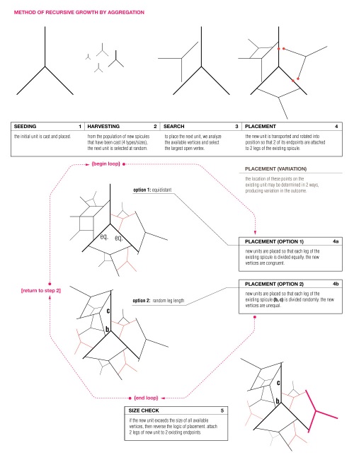
1. SEEDING:
The first spicule unit is cast and set into place.
// {begin loop} //
2. HARVESTING:
New spicules are continually being cast in 4 unit sizes. From this population of varying sizes, the next unit to be placed is chosen at random.
3. SEARCH:
To find a location for the new piece, the spicules which have already been placed are measured for the largest available open vertex. If no open vertex is large enough to accommodate the new unit, then proceed to step 5.
4. PLACEMENT:
The unit is transported and rotated into position so that 2 of its endpoints are in contact with 2 legs of an existing spicule. Due to the unequal angles of the unit (90/135/135), there are 2 possible rotational placements within any given vertex.
In addition, there are 2 possible methods for determining the location of the new endpoints along the existing legs. With Option 1 (4a) both endpoints of the new unit are placed at an equal distance from the vertex. In Option 2 (4b) one endpoint is placed at a random distance (B) from the vertex, and the other falls where it may (C) along the opposite leg.
5. SIZE CHECK:
If it is determined that the new unit exceeds the size of all available vertices, then the logic of placement is reversed. First, all endpoints are analyzed to find the furthest pair that will fit within the vertex of the new unit. These 2 points will necessarily be from 2 different spicules, which breaks the logic of subdividing and allows the system to grow in a new direction. The new spicule is placed so that these two endpoints are now inside of one of its angles, in contact with 2 of its legs.
// {end loop} //
// {return to step 2} //
Categories: Matthew Lutz
Some other simulation with 9 machines working in different behaviors.


Categories: Chi-Chen Yang
9 agents stack up 3 intersected cube structures.


Categories: Chi-Chen Yang
Three agents(machines) stacking up a tube-like structure.


Categories: Chi-Chen Yang
Three agents(machines) working, tries to get near to each other and stack up.


Categories: Chi-Chen Yang
Three agents making glass drops by turn, each one put the tail on the head of the one behind it.
Each agent chase the agent in front of it and avoid the one behind it.


Categories: Chi-Chen Yang
Processing:
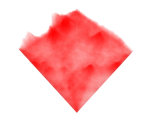
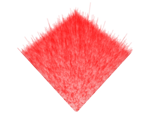
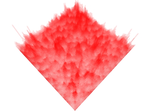
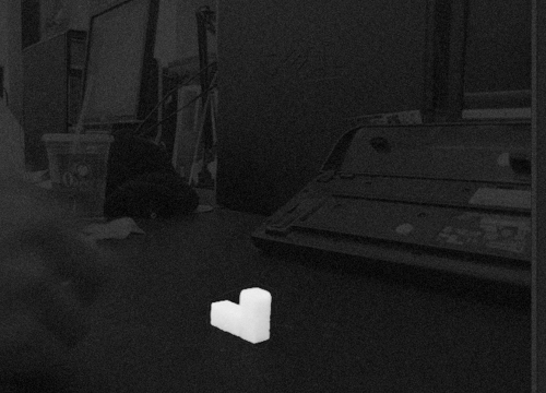
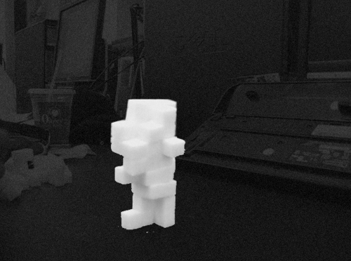
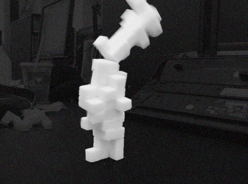
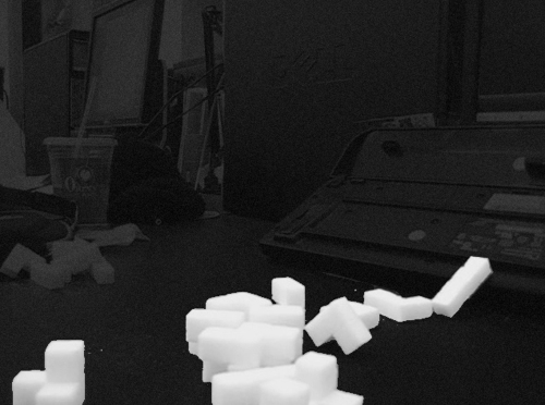
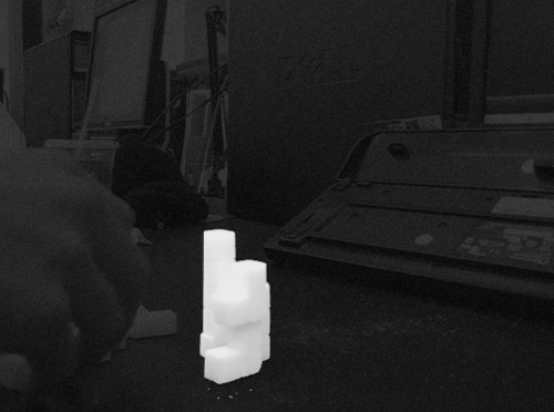
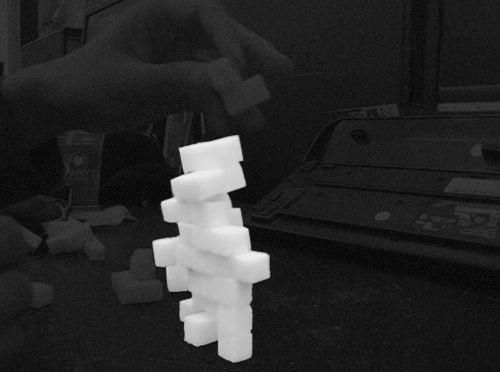
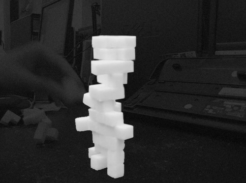
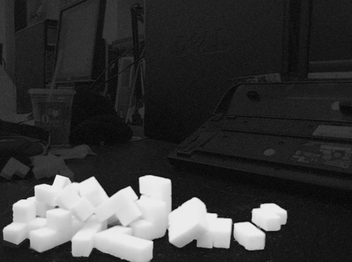
Sugar Cubes (4x Module) (Glueless):
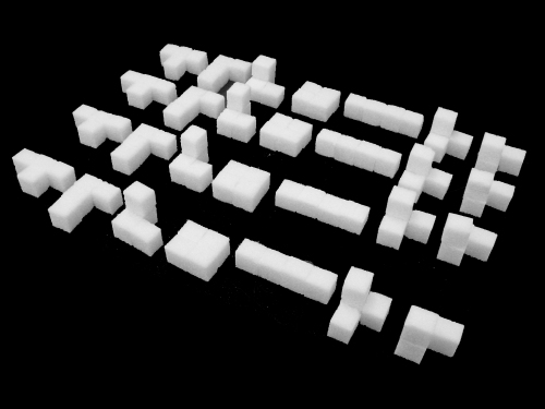
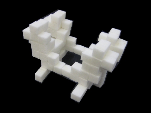
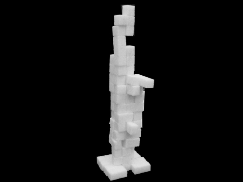
Robot:


Categories: Thad Nobuhara
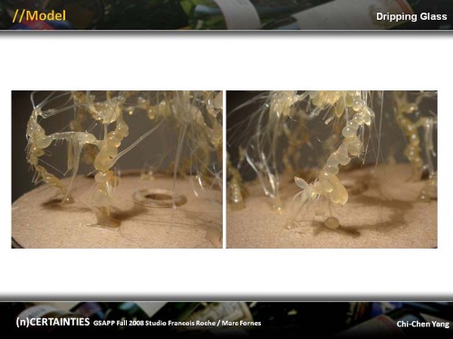
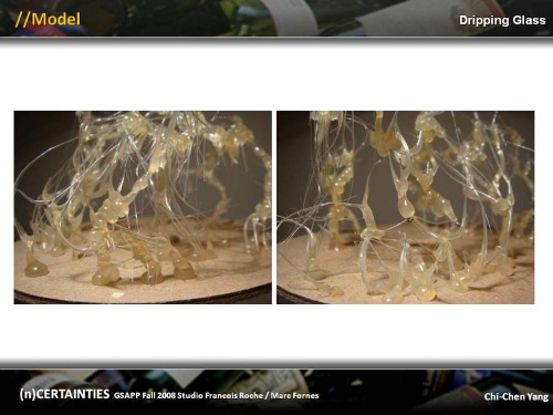
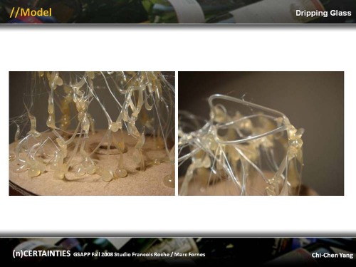
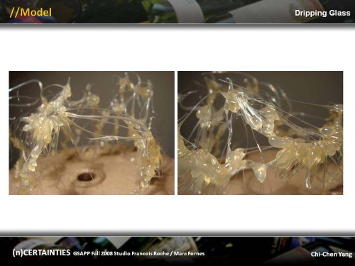
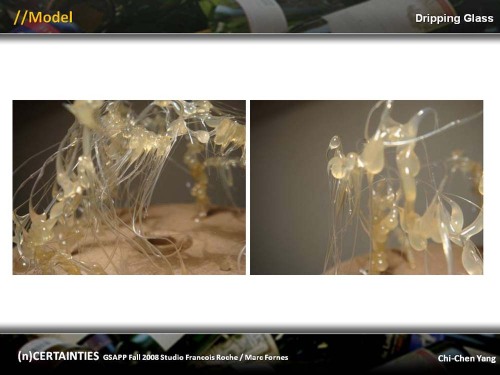
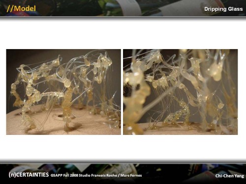
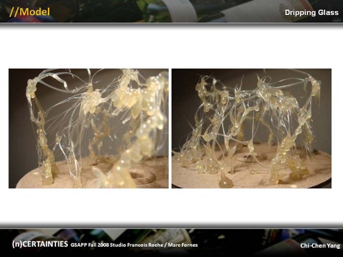
Model made with hot glue gun in order to experiment and simulate the dripping glass condition.
Categories: Chi-Chen Yang
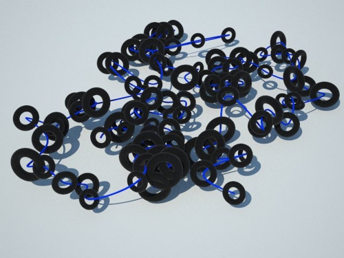
The first step I took to define the scenario and the trajectory was to generate a script able to create several generations of torus at different heights and not only in horizontal planes. The script is also printing the center of each torus to draw a curve through this cloud of points as a first approach for a trajectory.

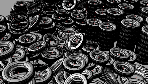
 Then I decided to generate a “real” tire cemetry considering actual tire shapes to get their centers, radius and orientation to design a trajectory that collects them.
Categories: Eduardo Mayoral
Tagged: aad, columbia, Eduardo Mayoral, GSAPP, ncertainties, rubber, tire, tire cemetery, trajectory
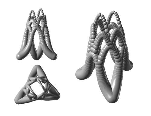
Robots Build to each other to make vaults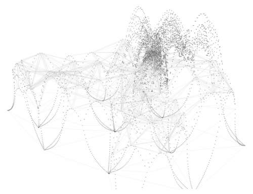
It Breaks at a larger scale
Categories: Mathew Staudt
Tagged: Paper Weigts


