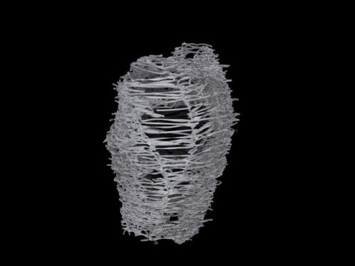
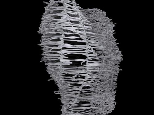
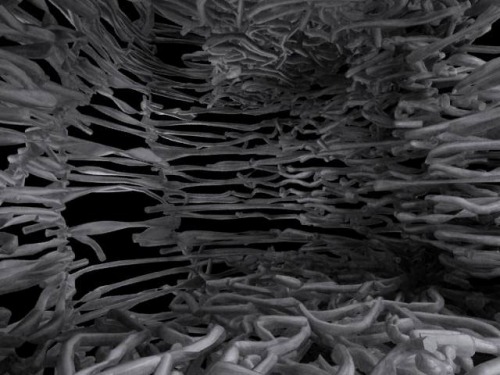
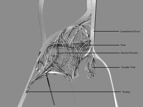
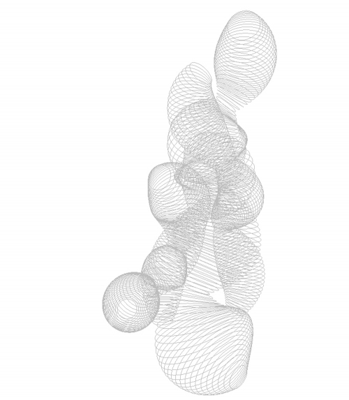
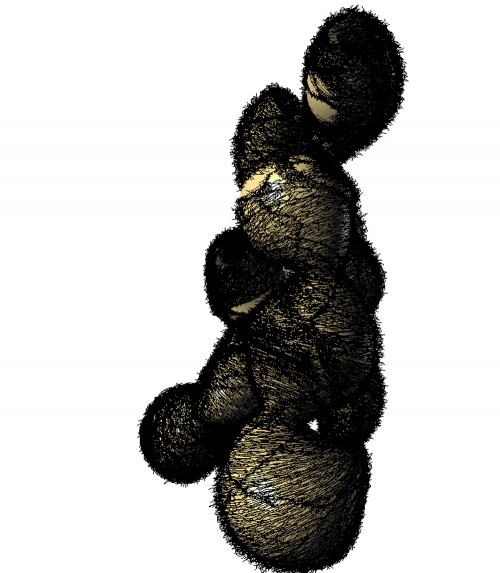
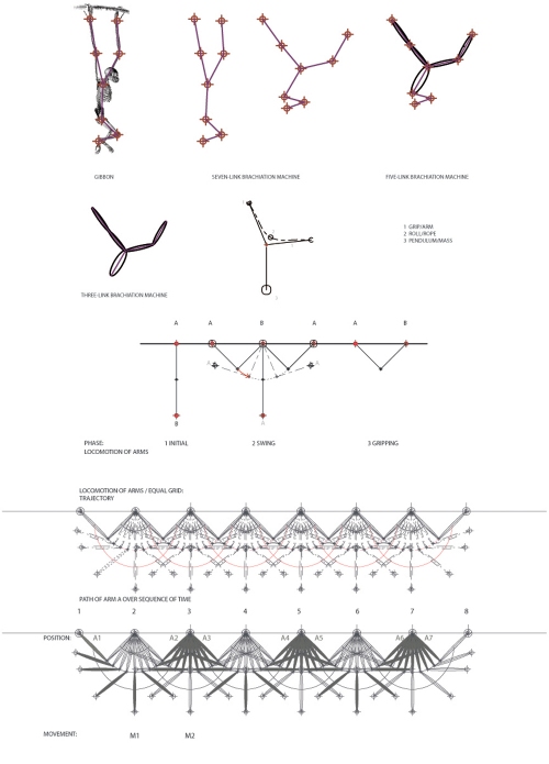
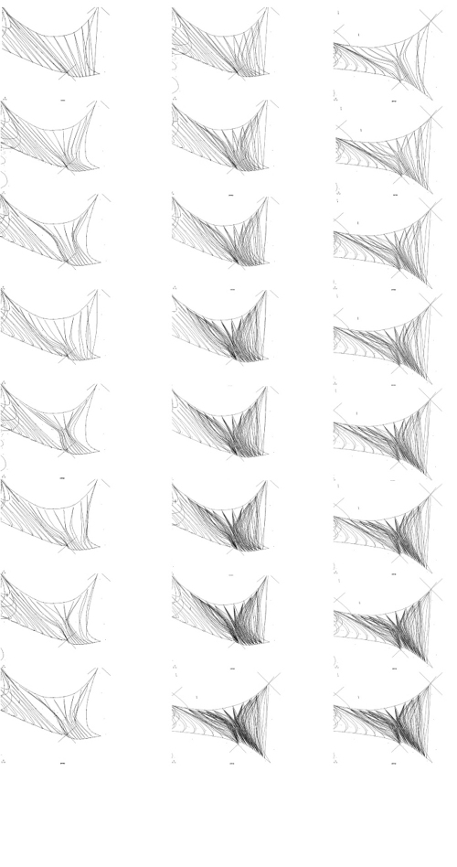
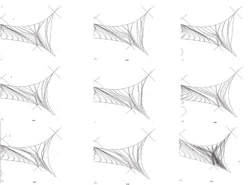
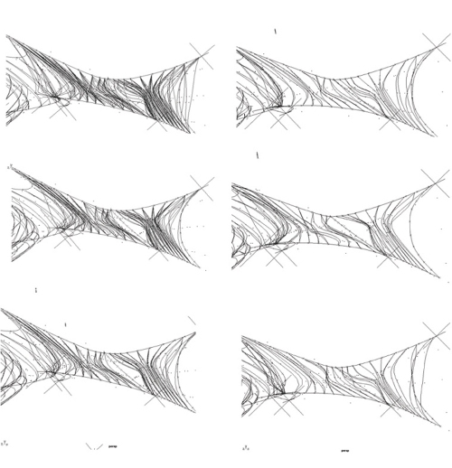
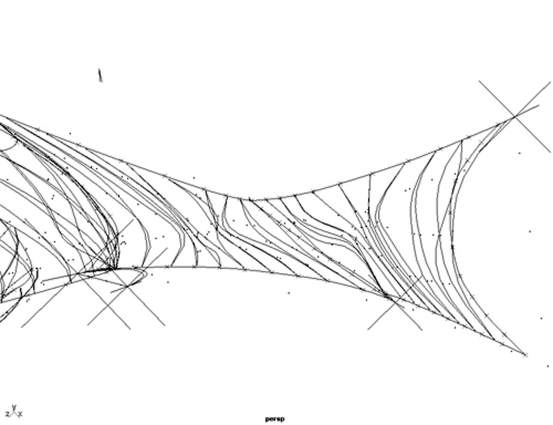
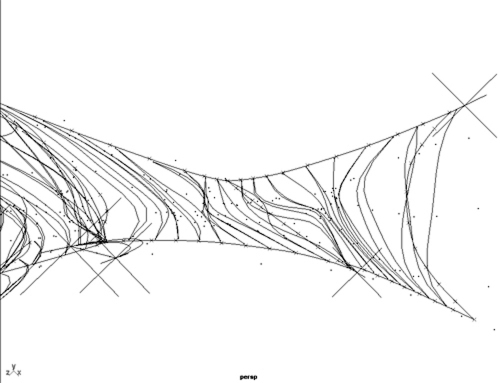
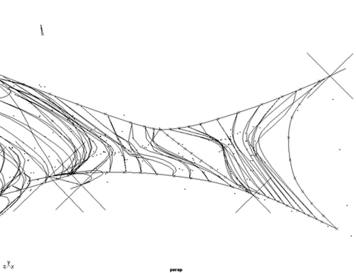
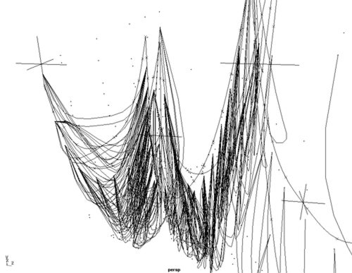
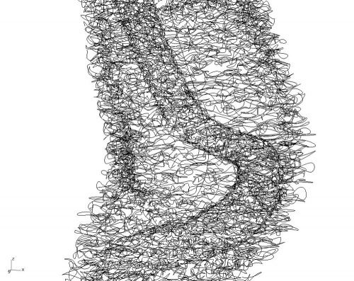
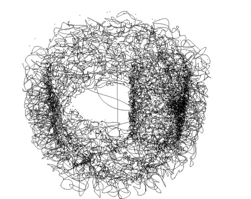
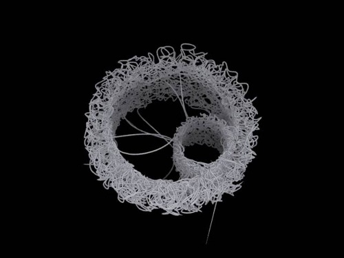
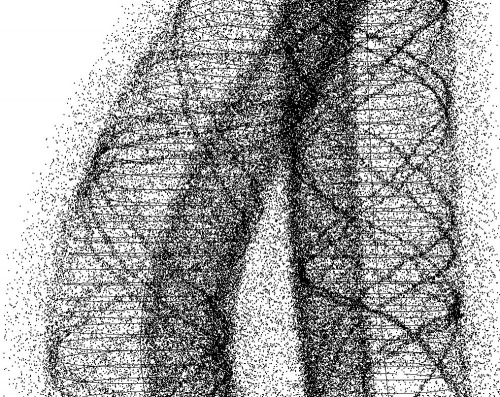
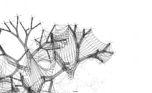
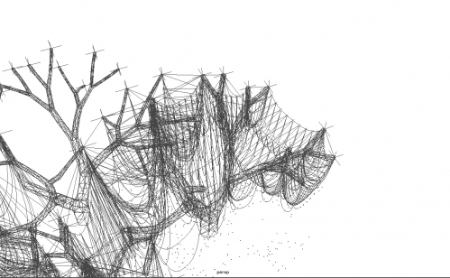
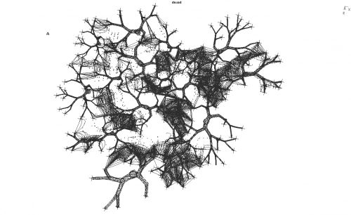
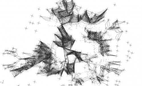
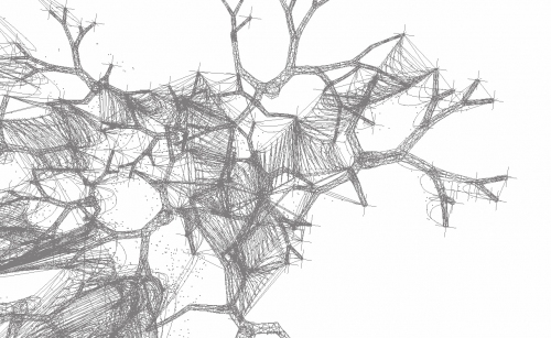
glass dripping substance model
November 22, 2008 · Leave a Comment
→ Leave a CommentCategories: Chi-Chen Yang
glass dripping trajectory
November 22, 2008 · Leave a Comment
→ Leave a CommentCategories: Chi-Chen Yang
SL_gradient ornamentation 2
November 21, 2008 · Leave a Comment
→ Leave a CommentCategories: Sungyong Lee
SL_tires_gradient ornamentation
November 19, 2008 · Leave a Comment
→ Leave a CommentCategories: Sungyong Lee
TN_111708 Bone Systems
November 17, 2008 · Leave a Comment
→ Leave a CommentCategories: Thad Nobuhara
Tagged: Bone, Nobuhara, Thad, Thad Nobuhara
rubber johnny 06
November 13, 2008 · Leave a Comment
The next step to modify the script is achieving a 3D shape for the canopy from the Voronoi pattern. The strategy will be to add normal vectors from the vertices of each cell within a range of height and draw curves using the points at the end of these normal lines as control points. Then applying a mesh patch command and offseting the mesh as a solid we will get the canopy in 3D with certain thickness. Drawing lines in plan using the control points of the cells, scaling them, creating a surface from a planar curve and extruding it as a solid we will get several holes in the canopy to generate different porosity conditions.


→ Leave a CommentCategories: Eduardo Mayoral
Tagged: columbia, Eduardo Mayoral, ncertainties, rubber, rubber johnny, tires
rubber johnny 05
November 10, 2008 · Leave a Comment
These are several plans showing how the current script behaves at the moment. Given a cloud of points that are the center of the tires and selecting a starting point, it draws a line which distance is within a range of a maximum and a minimum that you can choose. Then it checks the distance between the end point of this line and the rest of the points finding the closest one. After, it draws a line from the starting one to the last one mentioned and repeats this process creating several generations. You can slecet the number of generations at the begining. When the trajectory is done it draws a curve from this polyline and then it applies the Voronoi command. It draws curves considering the vertices of each Voronoi cell as control points generating areas that will be used as structural piles of tires. In between them tires will be smashed by the robot following the voronoi lines that separate each cell. Some curves are created in between and divided obtaining more points to apply the Voronoi command again generating a more sofisticated pattern for the surface of the canopy generated above.
→ Leave a CommentCategories: Eduardo Mayoral
Tagged: columbia, Eduardo Mayoral, ncertainties, rubber, rubber johnny, tires
rubber johnny 04
November 10, 2008 · Leave a Comment
This is an option where arises the possibility to design a racing track using melted rubber (which is an actual way of recycling tires) and create a program in its sorroundings protected by columns of tires that could have to do with temporary accomodation for spectators, facilities for the circuit, boxes, steps, housing…
→ Leave a CommentCategories: Eduardo Mayoral
Tagged: columbia, Eduardo Mayoral, ncertainties, rubber, tires
JA_Working on complexity_1
November 7, 2008 · Leave a Comment
→ Leave a CommentCategories: José Aragüez
TN_trajectories_test_A
November 6, 2008 · Leave a Comment
Rules:
_50 “triangle” robots (of same size) given random start point at base (dotted blue circles)
_Each robot given different random starting direction/orientation of bone extrusion.
_Each robot given same speed and achieve same height per iteration
_Each robot given same boundary sphere (blue sphere at top of drawing)
Condition 1_If robot’s boundary sphere should ever intersect with another, then change orientation to ’snap’ together at same moment (In DRAWING see thickness of red line). New orientation is established as average of combined robot trajectories (ex: (robot traj A + robot traj B)/2 = new robot traj). There is no set amount of nesting of robots, the more the merrier (allows for higher structural dexterity). (NOTE: (highest nesting of robots achieved thus far was 5)
Condition 2_ If robot’s boundary sphere does NOT come in contact with another robot boundary sphere for 5 phases, change direction (to hopefully find another robot)
_ If robots are snapped for 5 phases, “un-fuse” and take new random orientation (to allow for search for other robots allowing for stronger structural stability of system)
Possibilities (in order of hierarchy):
_ increase connectivity of system by either increasing the density of robots, shrinking boundary of initial scatter, or increasing ’scope’ of robots’ blue boundary sphere. Least time consuming is to increase ’scope’ of robots’ blue boundary sphere
_ Condition 3_ return to base_ Would allow for highest density at base and least density at top of system_ Originally was conceived to provide increased thickness of bone members closest to the base but since “stacking” bone on top of bone is no longer perceived as possible, would alow for a higher concentration of density towards base (in other words tying back bone to original base to allow more connections to ground plane / higher structural support, and also sustance renewal while their.
_ Condition 4_ If robot has not found a partner for ‘10′ phases, commit suicide (useless to the system) (will get rid of ‘floating’ strands) _ currently no protocal for termination
_ Condition 5_ porosity _ cinnamin bun swirl protocal?
_ Condition 6_ substance renewal _ maybe solved by condition 3
To FR + MF: Please email me immediately if you have any comments that could drastically change the outcome of system and/or if any other these conditions seem contradictory to the system. I will try to post again by sat afternoon with trajectory test B.
→ Leave a CommentCategories: Thad Nobuhara
SL_tire_cutting recent work
November 6, 2008 · Leave a Comment
→ Leave a CommentCategories: Sungyong Lee
LC_Recent Works
November 5, 2008 · Leave a Comment
→ Leave a CommentCategories: Leuyu Chen
Tagged: straw
glass space, wall & ramp
November 5, 2008 · Leave a Comment
→ Leave a CommentCategories: Chi-Chen Yang


